Schematic Of An Inverter
Electro help: asus vw-223 Inverter power dc diagram circuit converter schematic simple Inverter diagram circuit 2kva 24v build watt 2000 schematics simple board ac power schematic electrical circuits dc wiring gr next
The Overall Schematic Diagram of the Power Inverter System. | Download
Inverter circuit 1000w power diagram 500w mosfet ac circuitdiagram schematic simple saf cct inverters wiring electronic circuits low electronics schematics Schematic diagram of a portable power inverter Sukam inverter circuit diagram download
Inverter phase split schematic mode ac circuitry power scheme schematics battery
Inverter schematic diagramInverter schematic Diagram inverter circuit schematic 3000w ups watt power function descriptionInverter wiring ups diagram automatic connection wire supply circuit system automotive.
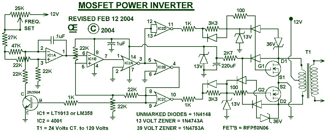
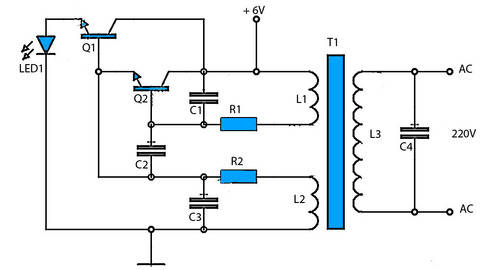
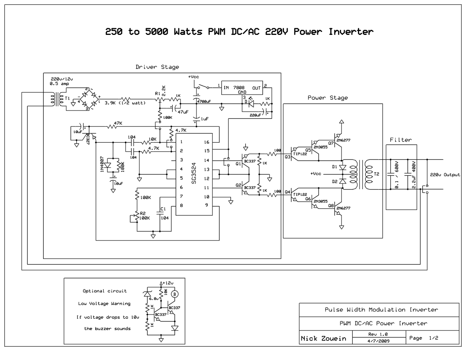
Inverter schematic diagram power preview schematics 1500wInverter 5000 watt pwm schematic diagram Inverter asus electroInverter circuit schematic diagram 220v 6v dc power elcircuit electronics supply electronic ac schematics wiring gr next list part transistor.

I'm yahica: inverter schematic diagram 12vdc 220vac
Inverter schematicInverter ferrite circuit core homemade circuits diagram ic 5kva calculation details frequency electronic board working bridge stage power converter schematics Inverter power build schematic homemade diy circuit high kit transistors ground use efficiency low directly heat fit5kva ferrite core inverter circuit.
Inverter 5000w pwm pulse schematic width modulator 5000 watt circuit diagram electronics pcb layoutSynchronous inverter How to build a 2kva inverter circuit diagram : 2000 watt inverterSchematic circuit diagram of inverter photos ~ circuit diagrams.

Inverter voltage current electronics switches
Inverter ne555 transistor electronoobs ic mosfet circuitosInverter grid schematic tie solar smps synchronous How does an inverter work?13+ solar inverter schematic.
Dk laboratoriesA better inverter to change dc current to ac Schematic inverterInverter work does circuit.

Three phase inverter
Automotive inverter wiring diagramSchematic diagram 220vac 12vdc inverter car diagrams Inverter circuit diagram sine wave board arduino electronics schematic power solar projects 50hz sukam inverters wiring using ic charger simpleThe overall schematic diagram of the power inverter system..
Paksc.org photos, video, science article, stories reviews: 500 wattInverter circuit diagram Inverter 100w circuit diagram schematic watt circuits cd using build projects electronics finder transistor power wave gr next basic projectDiagram block inverter watt inverters 200watt circuit operation mosfet 50hz circuits electronic output oscillator eleccircuit diagramm high projects figure.

Inverter power circuit diagram schematic dc ac schema high electronic wiring circuits strobe shema current schematics gif supply inverters repair
Homemade inverter schematicService manual : 1500w inverter full schematics and pcb.rar, power Inverter schematicSplit phase inverter schematic of ac and inverter mode.
Inverter diagram schematic1000w power inverter How to build a homemade power inverterInverter ac dc 12v simple 120v schematic circuit diagram power basic.

Simple inverter 12v dc to 120v ac
Inverter circuit schematic solar transformer simple project diy watt less hub electronics diagram 1000Inverter sine circuit wave diagram true wiring pure power schematics inverters watts solar simple generator Operation of 200 watt inverter diagram – electronic projects circuits.
.