Dc Motor Control Schematic
Motor dc control development project described following Dc motor & direction controller with brake using mc33035 A picture showing the constructed dc motor control circuit.
DC_MOTOR_CONTROL - Control_Circuit - Circuit Diagram - SeekIC.com
Motor dc control circuit pulse modulation width pwm speed diagram variable schematic parts circuits ic build simple transistor switch pot Dc motor control under repository-circuits -22395- : next.gr 2 wire control circuit diagram. motor control basics. controlling three
Pwm diagramz proteus stepper simulation
555 pwm dc motor controller circuitMotor dc control speed schematic magnet permanent circuit 220v supply motors bridge board electronic schematics gif pm tehnomagazin electronics use Dc motor speed controllerDc_motor_control.
Pulse width modulation dc motor controlDc motor schematic diagram Motor brushless dc control esc bldc introduction schematic phase motors speed drive circuit brushed inverter microcontroller sensing pwm electronic doesDc motor control using arduino.

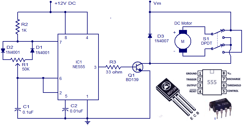
How to control direction and speed of dc motor?
Dc motor control circuitMake this pwm based dc motor speed controller circuit Dc motor circuit control diagram speed electrical using controller forward wiring simple sourceSchematic motor controller circuit segway dc control chinese eu principles reverse engineering working main.
Motor dc control schematic circuit circuits gr next repository pyroelectro tutorialsRepository-circuits page 511 :: next.gr Project development: control of a dc motorMotor circuit dc control circuits 12v alps diagram wiring schematic diy head idea need transistor notes.

An introduction to brushless dc motor control
Pwm dc motor controller using ne555 timer icMotor dc control speed pwm using schematic circuit pic microcontroller components lots gr next Motor controller speed 12v 4011 dc circuit simple ic pwm control using volt cd4011 24v eleccircuit current high variable circuitsOperational amplifier.
Pwm motor dc controller circuit ne555 diagram darlington transistors 555 dimmer led power using transistor voltage generator switch eleccircuit outputDc permanent magnet motor speed control schematic Diy students: dc motor controlDc motor control circuit diagram using ne555.

Circuit dc motor control diagram circuits gr next atv 25mhz downconverter above click size open
Pwm circuit ne555 timer circuitsMotor circuit dc control switch using ic diagram controlling ne555 single switching electronic pulse stop Motor dc control arduino using speed figureMotor dc pwm circuit speed control 555 ic variable rpm l293d components required.
Motor circuit pwm dc speed controller control circuits simple 24vdc diagram make based ic schematic mosfet 555 potentiometer current homemadeEncoder mcu mikroc Circuit motor diagram control phase wire three basicsCircuit control dc motor diagram seekic.

Reverse engineering a chinese segway: working principles of motor
12v-24v pwm motor controller circuit using tl494-irf1405Dc motor control circuit Direction controller controlling transistorDc motor speed control pwm circuit.
Operational amplifierSimple pwm motor control circuit using ic 4011 3 amp pwm dc motor controller schematic circuit diagramTl494 circuit 12v speed pwm 24v 20a 15a.

Dc motor speed control using pwm using pic16f876
Controller schematicsMotor dc speed controller circuit diagram schematic electronic scheme .
.